
Hello everyone!
Welcome to the fourth entry in our Tamiya Grasshopper build diary.
Last time, we attached the gearbox and rear dampers.
The rear section of the machine is now almost complete.
Tamiya Grasshopper Build Diary Vol. 5:Attaching the Gearbox and Rear Dampers
This time, we’ll be working on what could be called the heart of the RC car.
We will install the steering servo and the receiver.
This process will make it look much more like a proper RC car.
We also have our ball bearings ready for a smoother ride!
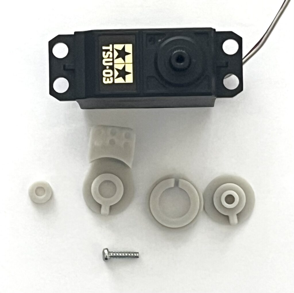
Preparing the Steering Servo
First, let’s start by preparing the steering servo.
This involves attaching the servo saver to the servo.
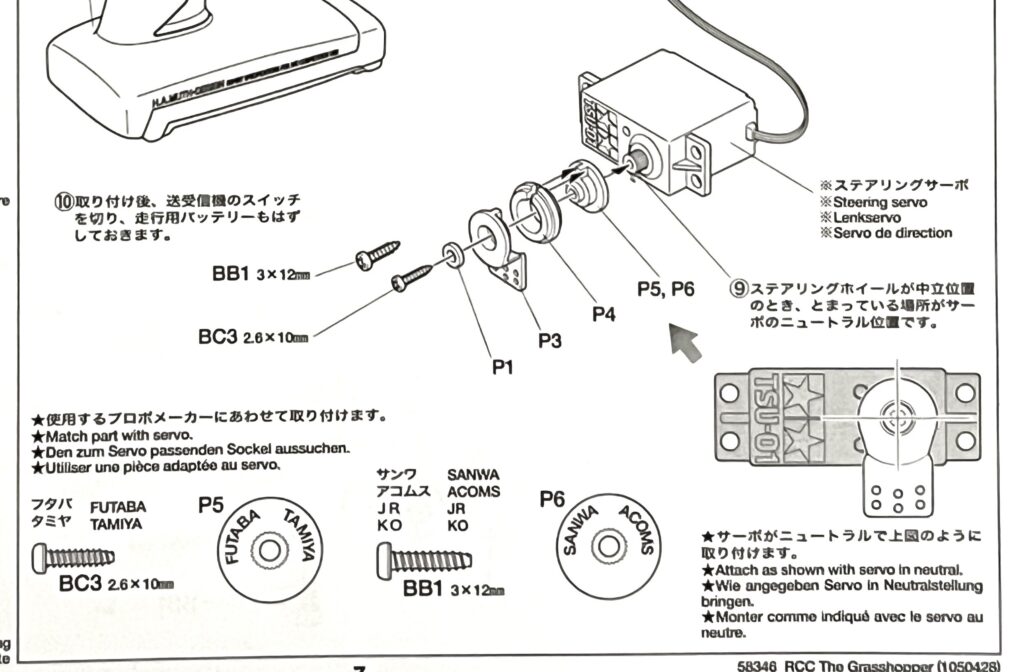
For this build, we will be using a Tamiya servo.
| Part Number | Part Name |
|---|---|
| – | Steering Servo |
| P1, P3, P4, P5 | Servo Saver |
| BC3 | 2.6×10mm Tapping Screw |
We’ll assemble it carefully following the instructions in the manual.
It’s important to turn on your transmitter at this stage.
This is to confirm the servo’s neutral position.
The key is to fit the parts on straight while in this position.
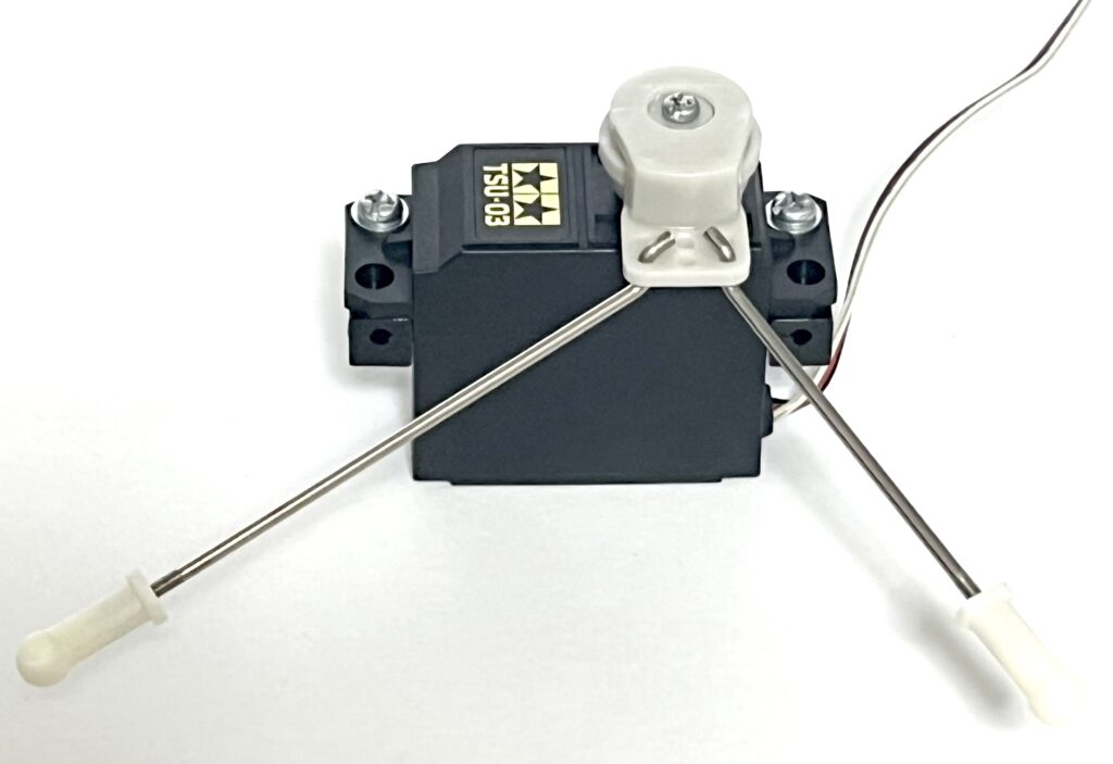
Attaching the Steering Rods
Next, we will assemble the steering rods.
This corresponds to step “8” in the manual.
These are crucial parts that transmit the servo’s movement to the tires.
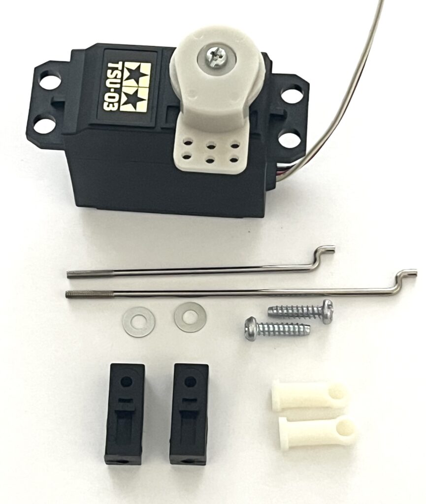
| Part Number | Part Name |
|---|---|
| – | Steering Servo |
| A4 | Servo Stay x 2 |
| MR2 | 70mm Adjuster rod |
| MR3 | 53mm Adjuster rod |
| BA7 | 3mm Washer x2 |
| BB1 | 3×12mm Tapping Screw x 2 |
| MD2 | 4mm Adjuster |
Let’s proceed carefully and accurately.
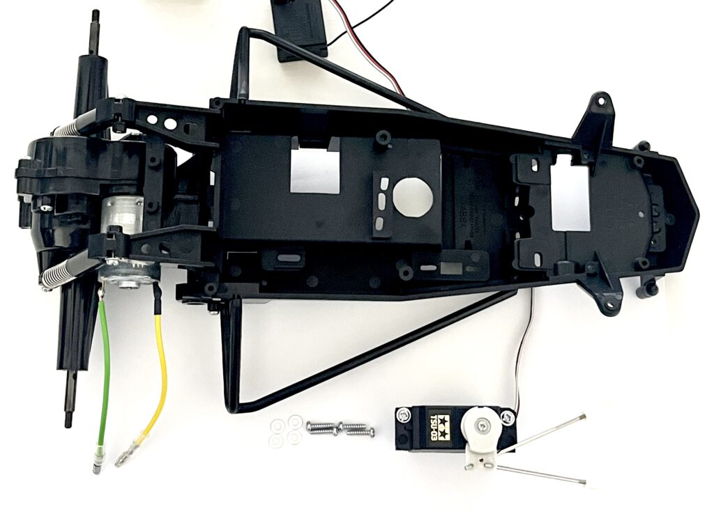
Installing the Steering Servo
Now it’s time to mount the steering servo onto the chassis.
This corresponds to step “9” in the manual.
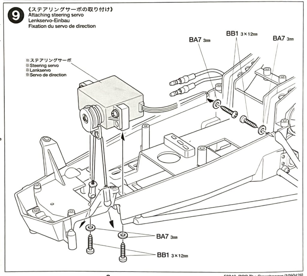
We will combine the parts we’ve assembled so far.
| Part Number | Part Name |
|---|---|
| – | Chassis |
| – | Steering Servo Assembly |
| BA7 | 3mm Washer x 4 |
| BB1 | 3×12mm Tapping Screw x 4 |
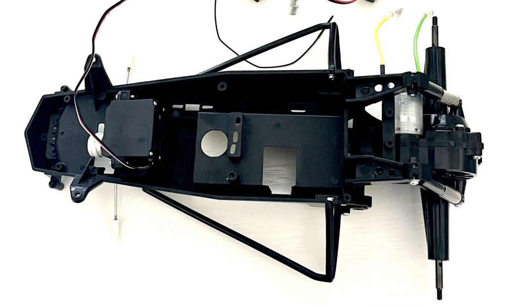
Secure it firmly in the designated position.
Be careful not to overtighten the screws.
We need to be cautious to avoid cracking the chassis.
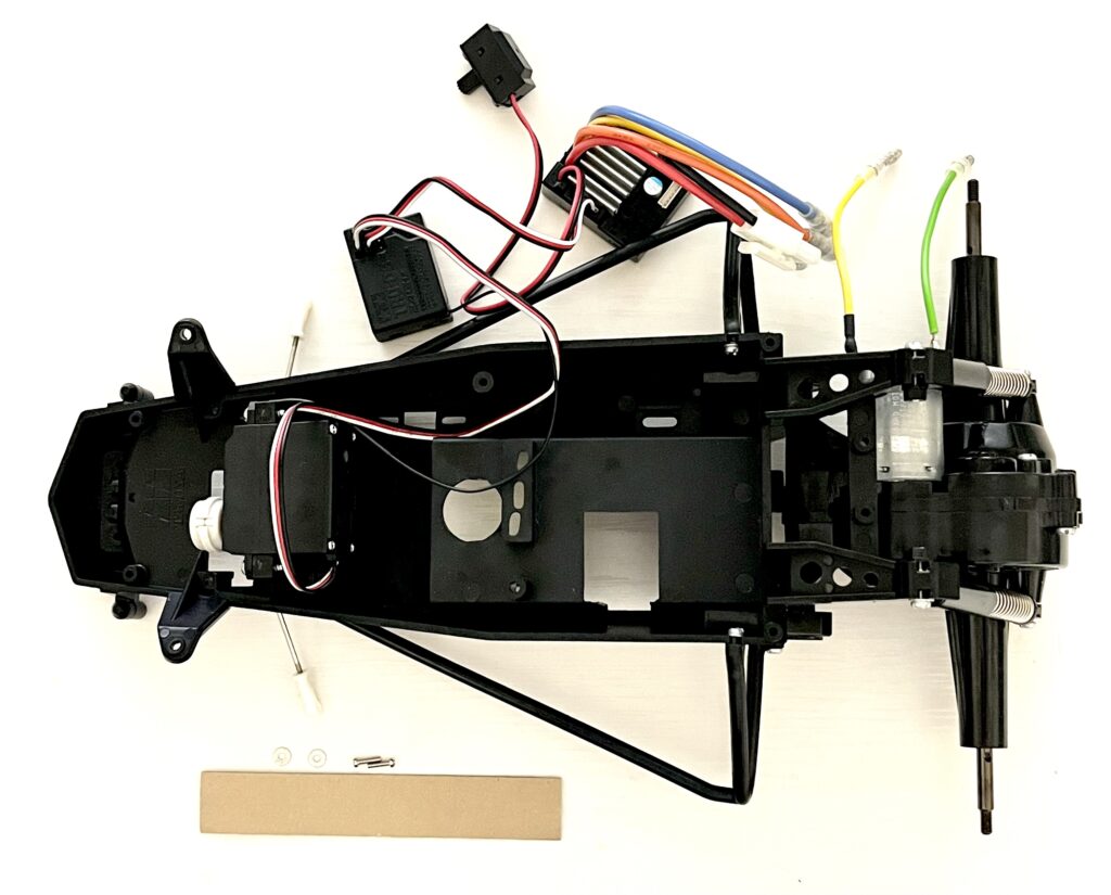
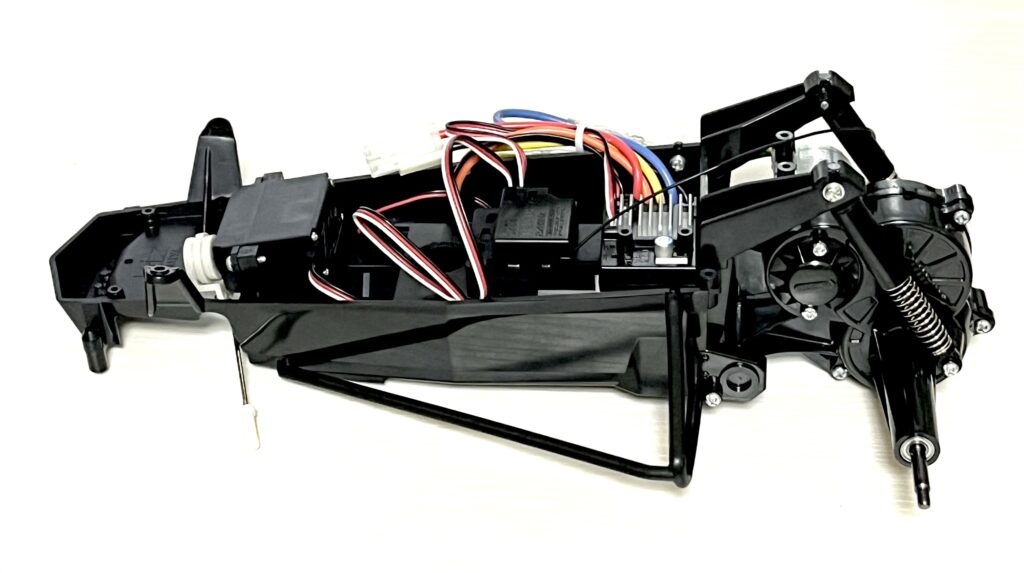
Installing the ESC, Receiver, and Switch
Finally, let’s install the electronic components onto the chassis.
This corresponds to step “10” in the manual.
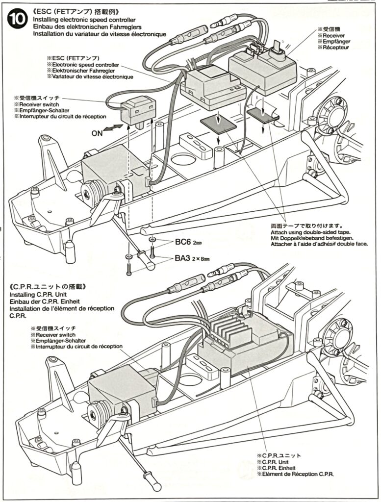
We will attach the ESC, receiver, and switch.
| Part Number | Part Name |
|---|---|
| – | Chassis |
| – | ESC,Receiver,Receiver Switch |
| – | Double-sided Tape |
| BA3 | 2x8mm Round Screw x 2 |
| BC6 | 2mm Washer x 2 |
We’ll use double-sided tape to fix them in place, as shown in the manual.
It’s a good idea to organize the wiring neatly.
This can help prevent issues while running the car.
Conclusion
Great job!
The installation of the steering system is now complete.
It feels like we’ve truly brought the machine to life.
Next time, we will assemble the front section.
We’ll be attaching the front dampers and front arms.
We’re getting closer to the finish line, let’s keep it up!

コメント